
Blog
2026 Best Steel Cable Tray for Global Buyers?
Choosing the 2026 Best Steel Cable Tray for Global Buyers requires more than comparing prices or catalogue photos. A suitable system must match cable weight, span length, ambient temperature, corrosion exposure, and installation conditions. This guide examines Steel Cable Tray options through practical engineering considerations, including material grade, surface treatment, load capacity, ventilation, accessories, and delivery reliability.
Real projects reveal important differences. A hot-dip galvanized tray may perform well in outdoor industrial areas, while stainless steel can offer stronger resistance in coastal or chemical environments. Indoor commercial projects may need a lighter, economical finish. Check the data carefully. Load ratings should reflect actual support spacing, not only laboratory figures. Tray width must also allow safe cable separation and future expansion.
Details matter.
Global buyers should request test reports, dimensional drawings, coating information, and installation guidance before placing an order. Relevant standards, such as IEC 61537, can support technical comparisons, but regional requirements still vary. A supplier’s factory experience, quality-control process, packaging method, and after-sales response deserve equal attention. One overlooked issue is local compatibility: fittings, bonding methods, fasteners, and electrical practices may differ between markets.
No tray is best everywhere. Even a technically strong product can fail when corrosion conditions, delivery routes, or site workmanship are underestimated. This introduction therefore encourages a balanced review of performance, cost, evidence, and long-term maintenance. Some assumptions may need revision after site inspection. That is not a weakness; it is responsible procurement.
What Is a Steel Cable Tray and How Does It Work?
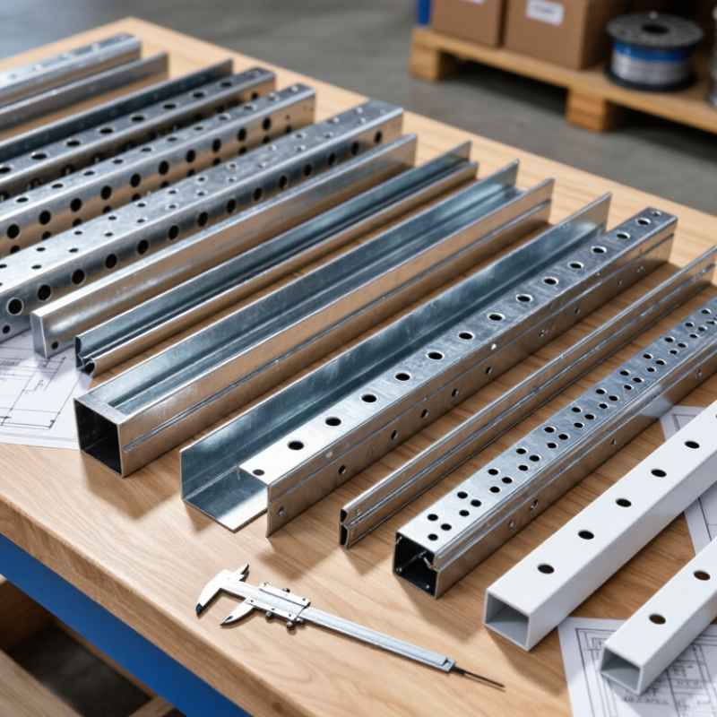
A steel cable tray is a metal support system that carries electrical, control, and communication cables. It is usually formed from galvanized or coated steel. Common designs include ladder, perforated, and solid-bottom trays. Each design suits a different installation environment.
The tray works by transferring cable weight to side rails, rungs, and mounting supports. Installers fix it to walls, ceilings, or structural frames using brackets and threaded rods. Cables rest inside the tray, while covers protect them from falling dust, impact, or moisture. Open rungs also improve airflow, which can help reduce heat around heavily loaded power cables.
I have seen poorly planned trays sag between supports. That mistake can damage cables over time. Engineers should check span length, load rating, cable separation, bending radius, and future capacity before installation. A tray should not be packed tightly. Leave practical space for inspection and additional cables. Bonding connections are also important because steel can support electrical continuity when correctly installed. However, tray metal alone should not be treated as a complete grounding method without project verification.
For outdoor or humid locations, corrosion protection deserves close attention. Galvanized steel may perform well, but coating quality and local conditions still matter. Buyers should request material details, tested load data, dimensional tolerances, and installation guidance. Small differences matter. A tray that looks strong may still fail when support spacing, cable weight, or environmental exposure is ignored.
2026 Best Steel Cable Tray for Global Buyers? - What Is a Steel Cable Tray and How Does It Work?
| Evaluation Dimension | Steel Cable Tray Type or Specification | Typical Technical Data | How It Works | Recommended Application | Key Buyer Consideration |
|---|---|---|---|---|---|
| Basic Definition | Steel cable tray system | Open support structure manufactured from formed steel sections, fittings, covers, and accessories | Supports and routes power, control, instrumentation, and communication cables while allowing ventilation and access | Commercial buildings, industrial facilities, infrastructure, energy, and data installations | Confirm cable quantity, cable weight, environmental exposure, span, and local installation requirements before selection |
| Ladder Tray | Steel ladder cable tray | Typical widths: 150–900 mm; typical side-rail height: 50–150 mm; common span: approximately 1.5–3.0 m | Longitudinal side rails and regularly spaced rungs carry cables and provide convenient tie-down points | Heavy power cables, industrial plants, substations, tunnels, and long straight cable routes | Offers strong ventilation and high cable accessibility; verify rung spacing for small or flexible cables |
| Perforated Tray | Perforated steel cable tray | Typical widths: 50–600 mm; typical side-rail height: 25–100 mm; perforated base supports cable fastening | Perforations allow cable ties, clamps, and ventilation openings while the tray base provides continuous cable support | Control cables, power distribution, building services, and mixed cable installations | A practical general-purpose option; check hole size, open-area ratio, and allowable load for the selected span |
| Solid-Bottom Tray | Solid-bottom steel cable tray | Typical widths: 100–600 mm; typical side-rail height: 50–100 mm; base has no continuous perforation | Provides continuous bottom support and greater physical separation from dust, falling particles, and nearby services | Low-voltage control, instrumentation, clean routing areas, and cables requiring additional mechanical support | Ventilation is lower than in ladder or perforated trays; cable derating and heat dissipation must be assessed |
| Wire Mesh Tray | Welded steel wire mesh tray | Typical widths: 50–600 mm; typical side height: 35–100 mm; supplied in modular straight sections and fittings | Welded wire grid supports cables, enables strong airflow, and permits cable exits at many points | Data centers, telecommunications, control systems, and short-to-medium cable routes | Lightweight and easy to modify; confirm wire diameter and load capacity for large or heavy cables |
| Material | Carbon steel | Common structural material; thickness often selected in the approximate range of 1.2–3.0 mm depending on load and span | Formed steel members resist bending and transfer cable loads to supports and building structures | Indoor commercial and industrial installations where corrosion exposure is controlled | Material thickness alone does not determine capacity; profile geometry, span, joints, and support configuration are also important |
| Surface Protection | Pre-galvanized steel | Zinc coating is applied to steel sheet before fabrication; coating mass varies by applicable standard and sheet grade | The zinc layer provides sacrificial corrosion protection for indoor and moderately controlled environments | Indoor buildings, electrical rooms, warehouses, and covered service areas | Cut edges and fabricated areas may require suitable corrosion protection; confirm coating specification with the project standard |
| Surface Protection | Hot-dip galvanized steel | Fabricated steel is immersed in molten zinc; coating thickness depends on steel thickness and the applicable galvanizing standard | A metallurgically bonded zinc coating protects the steel against atmospheric corrosion and provides sacrificial protection | Outdoor infrastructure, industrial plants, utility corridors, and humid environments | Inspect coating continuity, drainage holes, threaded connections, and compatibility with the installation environment |
| Surface Protection | Powder-coated or painted steel | Organic finish applied over prepared steel; color and coating system are project-specified | The coating forms a barrier against moisture and chemicals and can provide color identification | Indoor areas, architectural installations, and environments requiring color coordination | Surface preparation and coating adhesion are critical; damaged areas should be repaired according to the coating system |
| Corrosion Environment | Indoor dry environment | Low humidity and limited exposure to water, salt, chemicals, or industrial contaminants | Steel tray primarily provides mechanical support, with surface protection selected for expected indoor exposure | Office buildings, commercial facilities, electrical rooms, and enclosed plant areas | Pre-galvanized or suitably painted steel is commonly considered, subject to the project specification |
| Corrosion Environment | Outdoor or humid environment | Exposure may include rain, condensation, ultraviolet radiation, and temperature cycling | The tray system combines structural steel with a corrosion-resistant finish to maintain mechanical integrity over time | Roofs, bridges, external pipe racks, utility corridors, and open industrial areas | Hot-dip galvanizing or another project-approved corrosion system is generally evaluated; avoid water-retaining details |
| Corrosion Environment | Marine or chemically aggressive environment | Exposure may include salt spray, high humidity, acids, alkalis, or process chemicals | The tray must resist accelerated corrosion while maintaining support capacity and electrical bonding continuity | Coastal facilities, wastewater plants, chemical plants, offshore-related infrastructure, and food-processing areas | Material and finish should be selected through a documented corrosion assessment; stainless steel may be considered where required |
| Cable Capacity | Width selection | Common commercial widths range from approximately 50 to 900 mm; larger systems are available for engineered projects | Tray width determines the available cable arrangement space and helps prevent excessive crowding | All cable tray systems | Allow space for cable separation, installation access, future additions, bending radius, and required clearances |
| Cable Capacity | Fill planning | Actual allowable fill depends on cable type, heat dissipation, installation code, and cable arrangement | Open tray construction allows cables to be arranged for ventilation and maintenance without fully enclosing them | Power, control, instrumentation, and communication systems | Do not select tray width from cable diameter alone; check ampacity, grouping, segregation, and future capacity |
| Load Performance | Static load rating | Specified in force per unit length, commonly shown as N/m or kg/m, for a stated support span | Side rails, rungs, and tray bottoms transfer cable weight to brackets, hangers, or structural supports | All installations carrying cables or accessories | Compare load ratings only when span, tray width, support type, deflection limit, and test method are equivalent |
| Support Spacing | Horizontal support arrangement | Typical support spans are approximately 1.5–3.0 m, but the exact spacing depends on design load and manufacturer testing | Supports reduce bending and keep the tray within its permitted deflection and strength limits | Ceiling-mounted, floor-mounted, rack-mounted, and wall-mounted systems | Provide additional support near bends, tees, reducers, expansion joints, and heavy cable concentrations |
| Thermal Performance | Ventilated tray design | Ladder, perforated, and wire mesh trays provide more open area than solid-bottom designs | Airflow around cables helps dissipate heat and can support higher permissible current than enclosed routing, subject to code calculations | Power distribution and installations with significant heat generation | Cable ampacity must be calculated using the applicable electrical code and the actual cable grouping arrangement |
| Cable Protection | Tray cover | Available as solid, ventilated, peaked, or rain-shedding covers; material and finish should match the tray system | The cover reduces exposure to falling objects, dust, water dripping, sunlight, or accidental contact | Outdoor routes, industrial areas, traffic zones, and locations requiring additional cable protection | Check ventilation, cover retention, wind exposure, drainage, maintenance access, and added structural load |
| Electrical Bonding | Grounding and bonding provisions | Bonding may use listed bolted joints, bonding jumpers, or a separate protective conductor, depending on the system design | Continuity between metallic sections helps create a reliable path for fault current where the tray is designed as a bonding conductor | Metallic tray systems in low-voltage and industrial electrical installations | Follow the applicable electrical code; verify joint continuity, paint removal requirements, bonding jumpers, and fault-current capacity |
| Installation Geometry | Fittings and accessories | Common components include elbows, tees, crosses, reducers, vertical bends, couplers, brackets, clamps, and covers | Fittings maintain cable bend radius and provide continuous mechanical support through route changes | Complex building and industrial cable-routing layouts | Fitting radius must accommodate the minimum bending radius of the largest cable installed in the route |
| Standards and Testing | Product performance verification | Typical checks include load capacity, deflection, coating quality, dimensional accuracy, electrical continuity, and corrosion resistance | Testing and documented design data demonstrate that the tray can perform under specified installation conditions | International procurement and engineered projects | Request test conditions, declared support span, allowable deflection, material grade, coating details, and applicable standard references |
| Global Procurement | Technical documentation package | Recommended documents include dimensional drawings, load tables, material certificates, coating details, installation instructions, and packing lists | Documentation enables design approval, quantity calculation, installation planning, inspection, and international shipment verification | Export projects, EPC contracts, infrastructure tenders, and multi-country installations | Ensure units, tolerances, coating terminology, inspection criteria, and delivery configuration are clearly defined before purchase |
| Selection Priority | Best overall selection approach for 2026 projects | Match tray type, width, height, material, finish, load rating, support span, cover, and fittings to the actual site conditions | A correctly engineered system maintains cable support, ventilation, accessibility, protection, and long-term corrosion resistance | Global buyers comparing steel cable tray systems without relying on brand-specific data | The best tray is the one that satisfies the project load, environment, electrical, safety, installation, and documentation requirements—not simply the lowest-priced option |
Note: Dimensions, load ratings, support spans, coating requirements, cable fill, and grounding provisions are project-dependent. Final selection should be verified against the applicable national or international electrical, structural, corrosion-protection, and cable-management requirements.